


30 The Internal Geometry of Crystals

| Reference: | C. Kittel, Introduction to Solid State Physics, John Wiley and Sons, Inc., New York, 2nd ed., 1956. |
30–1The internal geometry of crystals
We have finished the study of the basic laws of electricity and magnetism, and we are now going to study the electromagnetic properties of matter. We begin by describing solids—that is, crystals. When the atoms of matter are not moving around very much, they get stuck together and arrange themselves in a configuration with as low an energy as possible. If the atoms in a certain place have found a pattern which seems to be of low energy, then the atoms somewhere else will probably make the same arrangement. For these reasons, we have in a solid material a repetitive pattern of atoms.
In other words, the conditions in a crystal are this way: The environment of a particular atom in a crystal has a certain arrangement, and if you look at the same kind of an atom at another place farther along, you will find one whose surroundings are exactly the same. If you pick an atom farther along by the same distance, you will find the conditions exactly the same once more. The pattern is repeated over and over again—and, of course, in three dimensions.
Imagine the problem of designing a wallpaper—or a cloth, or some
geometric design for a plane area—in which you are supposed to have a
design element which repeats and repeats and repeats, so that you can
make the area as large as you want. This is the two-dimensional analog
of a problem which a crystal solves in three dimensions. For example,
Fig. 30–1(a) shows a common kind of wallpaper design. There
is a single element repeated in a pattern that can go on forever. The
geometric characteristics of this wallpaper design, considering only its
repetition properties and not worrying about the geometry of the flower
itself or its artistic merit, are contained in
Fig. 30–1(b). If you start at any point, you can find the
corresponding point by moving the distance
The internal pattern of a crystal shows up in several ways. First, the binding strength of the atoms in certain directions is usually stronger than in other directions. This means that there are certain planes through the crystal where it is more easily broken than others. They are called the cleavage planes. If you crack a crystal with a knife blade it will often split apart along such a plane. Second, the internal structure often appears at the surface because of the way the crystal was formed. Imagine a crystal being deposited out of a solution. There are the atoms floating around in the solution and finally settling down when they find a position of lowest energy. (It’s as if the wallpaper got made by flowers drifting around until one drifted accidentally into place and got stuck, and then the next, and the next so that the pattern gradually grows.) You can appreciate that there will be certain directions in which it will grow at a different speed than in other directions, thereby growing into some kind of geometrical shape. Because of such effects, the outside surfaces of many crystals show some of the character of the internal arrangement of the atoms.
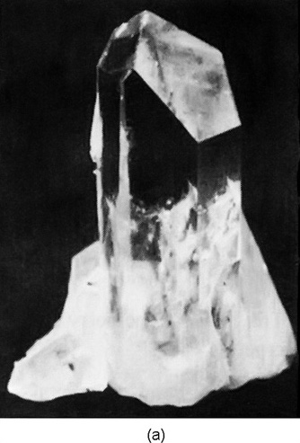
For example, Fig. 30–2(a) shows the shape of a typical
quartz crystal whose internal pattern is hexagonal. If you look
closely at such a crystal, you will notice that the outside does not
make a very good hexagon because the sides are not all of equal
length—they are, in fact, often very unequal. But in one respect it
is a very good hexagon: the angles between the faces are
exactly
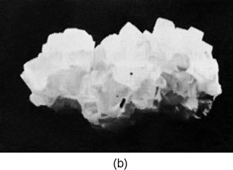
The internal geometry of a crystal of sodium chloride is also evident from its external shape. Figure 30–2(b) shows the shape of a typical grain of salt. Again the crystal is not a perfect cube, but the faces are exactly at right angles to one another.
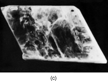
A more complicated crystal is mica, which has the shape shown in Fig. 30–2(c). It is a highly anisotropic crystal, as is easily seen from the fact that it is very tough if you try to pull it apart in one direction (horizontally in the figure), but very easy to split by pulling apart in the other direction (vertically). It has commonly been used to obtain very tough, thin sheets. Mica and quartz are two examples of natural minerals containing silica. A third example of a mineral with silica is asbestos, which has the interesting property that it is easily pulled apart in two directions but not in the third. It appears to be made of very strong, linear fibers.
30–2Chemical bonds in crystals
The mechanical properties of crystals clearly depend on the kind of chemical bindings between the atoms. The strikingly different strength of mica along different directions depends on the kinds of interatomic binding in the different directions. You have already learned in chemistry, no doubt, about the different kinds of chemical bonds. First, there are ionic bonds, as we have already discussed for sodium chloride. Roughly speaking, the sodium atoms have lost an electron and become positive ions; the chlorine atoms have gained an electron and become negative ions. The positive and negative ions are arranged in a three-dimensional checkerboard and are held together by electrical forces.
The covalent bond—in which electrons are shared between two atoms—is more common and is usually very strong. In a diamond, for example, the carbon atoms have covalent bonds in all four directions to the nearest neighbors, so the crystal is very hard indeed. There is also covalent bonding between silicon and oxygen in a quartz crystal, but there the bond is really only partially covalent. Because there is not complete sharing of the electrons, the atoms are partly charged, and the crystal is somewhat ionic. Nature is not as simple as we try to make it; there are really all possible gradations between covalent and ionic bonding.
A sugar crystal has still another kind of binding. In it there are large molecules in which the atoms are held strongly together by covalent bonds, so that the molecule is a tough structure. But since the strong bonds are completely satisfied, there are only relatively weak attractions between the separate, individual molecules. In such molecular crystals the molecules keep their individual identity, so to speak, and the internal arrangement might be as shown in Fig. 30–3. Since the molecules are not held strongly to each other, the crystals are easy to break. They are quite different from something like diamond, which is really one giant molecule that cannot be broken anywhere without disrupting strong covalent bonds. Paraffin is another example of a molecular crystal.
An extreme example of a molecular crystal occurs in a substance like solid argon. There is very little attraction between the atoms—each atom is a completely saturated monatomic molecule. But at very low temperatures, the thermal motion is very small, so the slight interatomic forces can cause the atoms to settle down into a regular array like a pile of closely packed spheres.
The metals form a completely different class of substances. The bonding is of an entirely different kind. In a metal the bonding is not between adjacent atoms but is a property of the whole crystal. The valence electrons are not attached to one atom or to a pair of atoms but are shared throughout the crystal. Each atom contributes an electron to a universal pool of electrons, and the atomic positive ions reside in the sea of negative electrons. The electron sea holds the ions together like some kind of glue.
In the metals, since there are no special bonds in any particular direction, there is no strong directionality in the binding. They are still crystalline, however, because the total energy is lowest when the atomic ions are arranged in some definite array—although the energy of the preferred arrangement is not usually much lower than other possible ones. To a first approximation, the atoms of many metals are like small spheres packed in as tightly as possible.
30–3The growth of crystals
Try to imagine the natural formation of crystals in the earth. In the earth’s surface there is a big mixture of all kinds of atoms. They are being continually churned about by volcanic action, by wind, and by water—continually being moved about and mixed. Yet, by some trick, silicon atoms gradually begin to find each other, and to find oxygen atoms, to make silica. One atom at a time is added to the others to build up a crystal—the mixture gets unmixed. And somewhere nearby, sodium and chlorine atoms are finding each other and building up a crystal of salt.
How does it happen that once a crystal is started, it permits only a
particular kind of atom to join on? It happens because the whole
system is working toward the lowest possible energy. A growing crystal
will accept a new atom if it is going to make the energy as low as
possible. But how does it know that a silicon—or an
oxygen—atom at some particular spot is going to result in the lowest
possible energy? It does it by trial and error. In the liquid, all of
the atoms are in perpetual motion. Each atom bounces against its
neighbors about
30–4Crystal lattices
The arrangement of the atoms in a crystal—the crystal lattice—can take on many geometric forms. We would like to describe first the simplest lattices, which are characteristic of most of the metals and of the solid form of the inert gases. They are the cubic lattices which can occur in two forms: the body-centered cubic, shown in Fig. 30–4(a), and the face-centered cubic shown in Fig. 30–4(b). The drawings show, of course, only one cube of the lattice; you are to imagine that the pattern is repeated indefinitely in three dimensions. Also, to make the drawing clearer, only the “centers” of the atoms are shown. In an actual crystal, the atoms are more like spheres in contact with each other. The dark and light spheres in the drawings may, in general, stand for different kinds of atoms or may be the same kind. For instance, iron has a body-centered cubic lattice at low temperatures, but a face-centered cubic lattice at higher temperatures. The physical properties are quite different in the two crystalline forms.
How do such forms come about? Imagine that you have the problem of
packing spherical atoms together as tightly as possible. One way would
be to start by making a layer in a “hexagonal close-packed array,”
as shown in Fig. 30–5(a). Then you could build up a
second layer like the first, but displaced horizontally, as shown in
Fig. 30–5(b). Next, you can put on the third layer. But
notice! There are two distinct ways of placing the
third layer. If you start the third layer by placing an atom
at
If the third layer has an atom at point
If a third layer is added to Fig. 30–5(b) by starting
with an atom at
Some metals—for example, copper and silver—choose the first alternative, the face-centered cubic. Others—for example, beryllium and magnesium—choose the other alternatives; they form hexagonal crystals. Clearly, which crystal lattice appears cannot depend only on the packing of little spheres, but must also be determined in part by other factors. In particular, it depends on the slight remaining angular dependence of the interatomic forces (or, in the case of the metals, on the energy of the electron pool). You will, no doubt, learn all about such things in your chemistry courses.
30–5Symmetries in two dimensions
We would now like to discuss some of the properties of crystals from
the point of view of their internal symmetries. The main feature of a
crystal is that if you start at one atom and move to a corresponding
atom one lattice unit away, you are again in the same kind of an
environment. That’s the fundamental proposition. But if you were an
atom, there would be another kind of change that could take you again
to the same environment—that is, another possible “symmetry.”
Figure 30–7(a) shows another possible “wallpaper-type” design
(though one you have probably never seen). Suppose we compare the
environments for points
There are other kinds of “equivalent” points in the pattern. For
instance, the points
Now that we have described some special examples, let’s try to figure
out all the possible symmetries a crystal can have. First, we consider
what happens in a plane. A plane lattice can
be defined by the two so-called primitive vectors that go from
one point of the lattice to the two nearest equivalent points.
The two vectors
We see that there are lattices which have a “four-sided”
symmetry. And we have described earlier a close-packed array based on
a hexagon which could have a six-sided symmetry. A rotation of the
array of circles in Fig. 30–5(a) by an angle
of
What other kinds of rotational symmetry are there? Can we have, for
example, a fivefold or an eightfold rotational symmetry? It is easy to
see that they are impossible. The only symmetry with more sides
than four is a six-sided symmetry. First, let’s show that more than
sixfold symmetry is impossible. Suppose we try to imagine a lattice with
two equal primitive vectors with an enclosed angle less than
What about fivefold symmetry? If we assume that the primitive vectors
Returning to Fig. 30–7(a), we see that the pattern has a fourfold
rotational symmetry. We have drawn in Fig. 30–7(b) another design
which has the same symmetry properties as part (a). The little
comma-like figures are asymmetric objects which serve to define the
symmetry of the design inside of each square. Notice that the commas
are reversed in alternate squares, so that the unit cell is larger
than one of the small squares. If there were no commas, the pattern
would still have fourfold symmetry, but the unit cell would be
smaller. The patterns of Fig. 30–7 also have other symmetry
properties. For instance, a reflection about any of the broken
lines
The patterns of Fig. 30–7 have still another kind of symmetry. If
the pattern is reflected about the line
These are all the possible symmetries in two dimensions. There is one
more spatial symmetry operation which is equivalent in two
dimensions to a
An inversion of pattern (a) of Fig. 30–9 produces a new pattern,
but an inversion of pattern (b) reproduces the same pattern. For a
two-dimensional pattern (as you can see from the figure), an inversion
of the pattern (b) through the point
If we characterize the “symmetry” of a pattern—or lattice—by the
kinds of symmetry operations we have been describing, it turns out that
for two dimensions
It is peculiar how few of the
30–6Symmetries in three dimensions
So far we have talked only about patterns in two dimensions. What we are
really interested in, however, are patterns of atoms in three
dimensions. First, it is clear that a three-dimensional crystal will
have three primitive vectors. If we then ask about the possible
symmetry operations in three dimensions, we find that there are
If one of the primitive vectors, say
If all three primitive vectors are at right angles, but of different
lengths, we get the orthorhombic cell. The figure is
symmetric for rotations of
The point of all this discussion about symmetries is that the internal
symmetries of the crystals show up—sometimes in subtle ways—in the
macroscopic physical properties of the crystal. For instance, a
crystal will, in general, have a tensor electric polarizability. If we
describe the tensor in terms of the ellipsoid of polarization, we
should expect that some of the crystal symmetries should show up also
in the ellipsoid. For example, a cubic crystal is symmetric with
respect to a rotation of
On the other hand, a tetragonal crystal has a fourfold rotational symmetry. Its ellipsoid must have two of its principal axes equal, and the third must be parallel to the axis of the crystal. Similarly, since the orthorhombic crystal has twofold rotational symmetry about three orthogonal axes, its axes must coincide with the axes of the polarization ellipsoid. In a like manner, one of the axes of a monoclinic crystal must be parallel to one of the principal axes of the ellipsoid, though we can’t say anything about the other axes. Since a triclinic crystal has no rotational symmetry, the ellipsoid can have any orientation at all.
As you can see, we can make a big game of figuring out the possible symmetries and relating them to the possible physical tensors. We have considered only the polarization tensor, but things get more complicated for others—for instance, for the tensor of elasticity. There is a branch of mathematics called “group theory” that deals with such subjects, but usually you can figure out what you want with common sense.
30–7The strength of metals
We have said that metals usually have a simple cubic crystal structure; we want now to discuss their mechanical properties—which depend on this structure. Metals are, generally speaking, very “soft,” because it is easy to slide one layer of the crystal over the next. You may think: “That’s ridiculous; metals are strong.” Not so, a single crystal of a metal can be distorted very easily.
Suppose we look at two layers of a crystal subjected to a shear force, as shown in the diagram of Fig. 30–11(a). You might at first think the whole layer would resist motion until the force was big enough to push the whole layer “over the hump,” so that it shifted one notch to the left. Although slipping does occur along a plane, it doesn’t happen that way. (If it did, you would calculate that the metal is much stronger than it really is.) What happens is more like one atom going at a time; first the atom on the left makes its jump, then the next, and so on, as indicated in Fig. 30–11(b). In effect it is the vacant space between two atoms that quickly travels to the right, with the net result that the whole second layer has moved over one atomic spacing. The slipping goes this way because it takes much less energy to lift one atom at a time over the hump than to lift a whole row. Once the force is enough to start the process, it goes the rest of the way very fast.
It turns out that in a real crystal, slipping will occur repeatedly at one plane, then will stop there and start at some other plane. The details of why it starts and stops are quite mysterious. It is, in fact, quite strange that successive regions of slip are often fairly evenly spaced. Figure 30–12 shows a photograph of a tiny thin copper crystal that has been stretched. You can see the various planes where slipping has occurred.
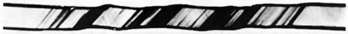
The sudden slipping of individual crystal planes is quite apparent if you take a piece of tin wire that has large crystals in it and stretch it while holding it next to your ear. You can hear a rush of “ticks” as the planes snap to their new positions, one after the other.
The problem of having a “missing” atom in one row is somewhat more difficult than it might appear from Fig. 30–11. When there are more layers, the situation must be something like that shown in Fig. 30–13. Such an imperfection in a crystal is called a dislocation. It is presumed that such dislocations are either present when the crystal was formed or are generated at some notch or crack at the surface. Once they are produced, they can move relatively freely through the crystal. The gross distortions result from the motions of many of such dislocations.
Dislocations can move freely—that is, they require little extra energy—so long as the rest of the crystal has a perfect lattice. But they may get “stuck” if they encounter some other kind of imperfection in the crystal. If it takes a lot of energy for them to pass the imperfection, they will be stopped. This is precisely the mechanism that gives strength to imperfect metal crystals. Pure iron crystals are quite soft, but a small concentration of impurity atoms may cause enough imperfections to effectively immobilize the dislocations. As you know, steel, which is primarily iron, is very hard. To make steel, a small amount of carbon is dissolved in the iron melt; if the melt is cooled rapidly, the carbon precipitates out in little grains, making many microscopic distortions in the lattice. The dislocations can no longer move about, and the metal is hard.
Pure copper is very soft, but can be “work-hardened.” This is done by hammering on it or bending it back and forth. In this case, many new dislocations of various kinds are made which interfere with one another, cutting down their mobility. Perhaps you’ve seen the trick of taking a bar of “dead soft” copper and gently bending it around someone’s wrist as a bracelet. In the process, it becomes work-hardened and cannot easily be unbent again! A work-hardened metal like copper can be made soft again by annealing at a high temperature. The thermal motion of the atoms “irons out” the dislocations and makes large single crystals again. We have, so far, described only the so-called slip dislocation. There are many other kinds, one of which is the screw dislocation shown in Fig. 30–14. Such dislocations often play an important part in crystal growth.
30–8Dislocations and crystal growth
One of the great puzzles for a long time was how crystals can possibly
grow. We have described how it is that each atom might, by repeated
testing, determine whether it was better to be in the crystal or not.
But that means that each atom must find a place of low energy. However,
an atom put on a new surface is only bound by one or two bonds from
below, and doesn’t have the same energy it would have if it were placed
in a corner, where it would have atoms on three sides. Suppose we
imagine a growing crystal as a stack of blocks, as shown in
Fig. 30–15. If we try a new block at, say, position
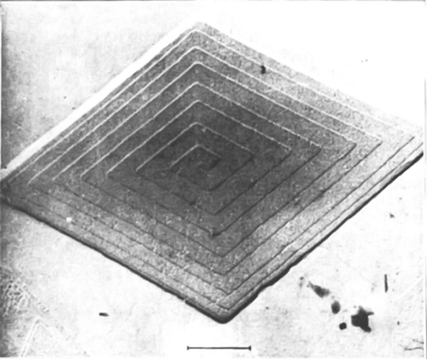
What happens, though, when that line is finished? To start a new line, an atom must come to rest with only two sides attached, and that is again not very likely. Even if it did, what would happen when the layer was finished? How could a new layer get started? One answer is that the crystal prefers to grow at a dislocation, for instance around a screw dislocation like the one shown in Fig. 30–14. As blocks are added to this crystal, there is always some place where there are three available bonds. The crystal prefers, therefore, to grow with a dislocation built in. Such a spiral pattern of growth is shown in Fig. 30–16, which is a photograph of a single crystal of paraffin.
30–9The Bragg-Nye crystal model
We cannot, of course, see what goes on with the individual atoms in a crystal. Also, as you realize by now, there are many complicated phenomena that are not easy to treat quantitatively. Sir Lawrence Bragg and J. F. Nye have devised a scheme for making a model of a metallic crystal which shows in a striking way many of the phenomena that are believed to occur in a real metal. In the following pages we have reproduced their original article, which describes their method and shows some of the results they obtained with it. (The article is reprinted from the Proceedings of the Royal Society of London, Vol. 190, September 1947, pp. 474–481—with the permission of the authors and of the Royal Society.)1
1. The bubble model
Models of crystal structure have been described from time to time in
which the atoms are represented by small floating or suspended magnets, or by
circular disks floating on a water surface and held together by the forces of
capillary attraction. These models have certain disadvantages; for instance, in
the case of floating objects in contact, frictional forces impede their free
relative movement. A more serious disadvantage is that the number of components
is limited, for a large number of components is required in order to approach
the state of affairs in a real crystal. The present paper describes the
behaviour of a model in which the atoms are represented by small bubbles from
2. Method of formation
The bubbles are blown from a fine orifice, beneath the surface of a soap
solution. We have had the best results with a solution the formula of which was
given to us by Mr Green of the Royal Institution.
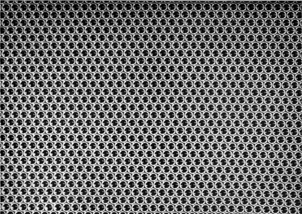
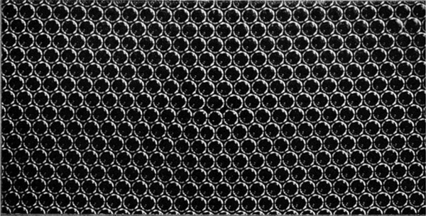
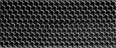
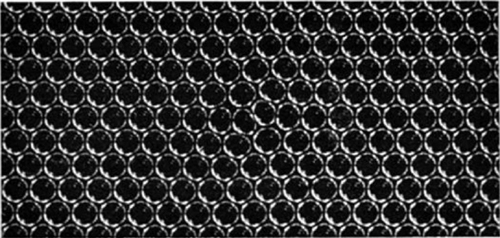
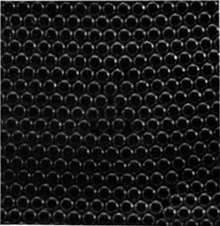
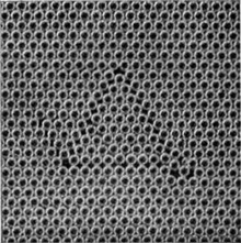
Figure 2, plate 8, shows a portion of a raft or two-dimensional crystal of
bubbles. Its regularity can be judged by looking at the figure in a glancing
direction. The size of the bubbles varies with the aperture, but does not appear
to vary to any marked degree with the pressure or the depth of the orifice
beneath the surface. The main effect of increasing the pressure is to increase
the rate of issue of the bubbles. As an example, a thick-walled jet of
With this apparatus we have not found it possible to reduce the size of the jet
and so produce bubbles of smaller diameter than
These two-dimensional crystals show structures which have been supposed to exist in metals, and simulate effects which have been observed, such as grain boundaries, dislocations and other types of fault, slip, recrystallization, annealing, and strains due to ‘foreign’ atoms.
3. Grain boundaries
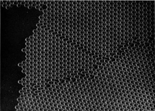
Figures 5a, 5b and 5c, plates 9 and 10, show typical
grain boundaries for bubbles of
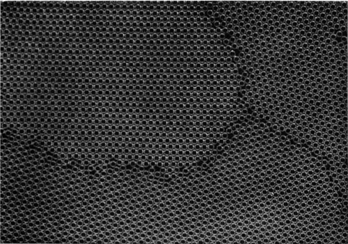
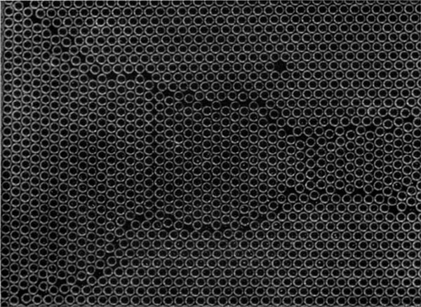
Separate grains show up distinctly when photographs of polycrystalline rafts such as figures 5a to 5c, plates 9 and 10, and figures 12a to 12e, plates 14 to 16, are viewed obliquely. With suitable lighting, the floating raft of bubbles itself when viewed obliquely resembles a polished and etched metal in a remarkable way.
It often happens that some ‘impurity atoms’, or bubbles which are markedly larger or smaller than the average, are found in a polycrystalline raft, and when this is so a large proportion of them are situated at the grain boundaries. It would be incorrect to say that the irregular bubbles make their way to the boundaries; it is a defect of the model that no diffusion of bubbles through the structure can take place, mutual adjustments of neighbours alone being possible. It appears that the boundaries tend to readjust themselves by the growth of one crystal at the expense of another till they pass through the irregular atoms.
4. Dislocations
When a single crystal or polycrystalline raft is compressed, extended, or otherwise deformed it exhibits a behaviour very similar to that which has been pictured for metals subjected to strain. Up to a certain limit the model is within its elastic range. Beyond that point it yields by slip along one of the three equally inclined directions of closely packed rows. Slip takes place by the bubbles in one row moving forward over those in the next row by an amount equal to the distance between neighbours. It is very interesting to watch this process taking place. The movement is not simultaneous along the whole row but begins at one end with the appearance of a ‘dislocation’, where there is locally one more bubble in the rows on one side of the slip line as compared with those on the other. This dislocation then runs along the slip line from one side of the crystal to the other, the final result being a slip by one ‘inter-atomic’ distance. Such a process has been invoked by Orowan, by Polanyi and by Taylor to explain the small forces required to produce plastic gliding in metal structures. The theory put forward by Taylor (1934) to explain the mechanism of plastic deformation of crystals considers the mutual action and equilibrium of such dislocations. The bubbles afford a very striking picture of what has been supposed to take place in the metal. Sometimes the dislocations run along quite slowly, taking a matter of seconds to cross a crystal; stationary dislocations also are to be seen in crystals which are not homogeneously strained. They appear as short black lines, and can be seen in the series of photographs, figures 12a to 12e, plates 14 to 16. When a polycrystalline raft is compressed, these dark lines are seen to be dashing about in all directions across the crystals.
Figures 6a, 6b and 6c, plates 10 and 11,
show examples of dislocations. In figure 6a, where the
diameter of the bubbles is
Figure 7, plate 11, shows three parallel dislocations. If we call them positive and negative (following Taylor) they are positive, negative, positive, reading from left to right. The strip between the last two has three bubbles in excess, as can be seen by looking along the rows in a horizontal direction. Figure 8, plate 12, shows a dislocation projecting from a grain boundary, an effect often observed.
Figure 9, plate 12, shows a place where two bubbles take the place of one. This may be regarded as a limiting case of positive and negative dislocations on neighbouring rows, with the compressive sides of the dislocations facing each other. The contrary case would lead to a hole in the structure, one bubble being missing at the point where the dislocations met.
5. Other types of fault
Figure 10, plate 12, shows a narrow strip between two crystals of parallel orientation, the strip being crossed by a number of fault lines where the bubbles are not in close packing. It is in such places as these that recrystallization may be expected. The boundaries approach and the strip is absorbed into a wider area of perfect crystal.
Figures 11a to 11g, plates 13 and 14 are examples of
arrangements which frequently appear in places where there is a local
deficiency of bubbles. While a dislocation is seen as a dark stripe in
a general view, these structures show up in the shape of the letter
V or as triangles. A typical V structure is seen in
figure 11a. When the model is being distorted, a V
structure is formed by two dislocations meeting at an inclination
of
Here and there in the crystals there is a blank space where a bubble is missing, showing as a black dot in a general view. Examples occur in figure 11g. Such a gap cannot be closed by a local readjustment, since filling the hole causes another to appear. Such holes both appear and disappear when the crystal is ‘cold-worked’. These structures in the model suggest that similar local faults may exist in an actual metal. They may play a part in processes such as diffusion or the order-disorder change by reducing energy barriers in their neighbourhood, and act as nuclei for crystallization in an allotropic change.
6. Recrystallization and annealing
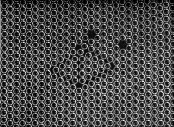
Figures 12a to 12e, plates 14 to 16, show the same raft of
bubbles at successive times. A raft covering the surface of the solution was
given a vigorous stirring with a glass rake, and then left to adjust itself.
Figure 12a shows its aspect about
A number of interesting points are to be seen in this series. Note the
three small grains at the points indicated by the co-ordinates
Figures 13a, 13b and 13c, plate 17, show a portion of
a raft
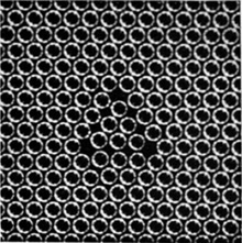
7. Effect of impurity atom
Figure 14, plate 18, shows the widespread effect of a bubble which is of the wrong size. If this figure is compared with the perfect rafts shown in figures 2 and 4, plate 8, it will be seen that three bubbles, one larger and two smaller than normal, disturb the regularity of the rows over the whole of the figure. As has been mentioned above, bubbles of the wrong size are generally found in the grain boundaries, where holes of irregular size occur which can accommodate them.
8. Mechanical properties of the two-dimensional model
The mechanical properties of a two-dimensional perfect raft have been described in the paper referred to above (Bragg 1942b). The raft lies between two parallel springs dipping horizontally in the surface of the soap solution. The pitch of the springs is adjusted to fit the spacing of the rows of bubbles, which then adhere firmly to them. One spring can be translated parallel to itself by a micrometer screw, and the other is supported by two thin vertical glass fibres. The shearing stress can be measured by noting the deflexion of the glass fibres. When subjected to a shearing strain, the raft obeys Hooke’s law of elasticity up to the point where the elastic limit is reached. It then slips along some intermediate row by an amount equal to the width of one bubble. The elastic shear and slip can be repeated several times. The elastic limit is approximately reached when one side of the raft has been sheared by an amount equal to a bubble width past the other side. This feature supports the basic assumption made by one of us in the calculation of the elastic limit of a metal (Bragg 1942a), in which it is supposed that each crystallite in a cold-worked metal only yields when the strain in it has reached such a value that energy is released by the slip.
A calculation has been made by M. M. Nicolson of the forces between the
bubbles, and will be published shortly. It shows two interesting points. The
curve for the variation of potential energy with distance between centres is
very similar to those which have been plotted for atoms. It has a minimum for a
distance between centres slightly less than a free bubble diameter, and rises
sharply for smaller distances. Further, the rise is extremely sharp for bubbles
of
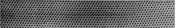
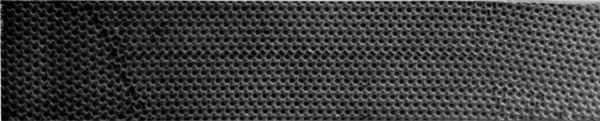
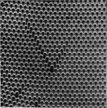
9. Three-dimensional assemblages
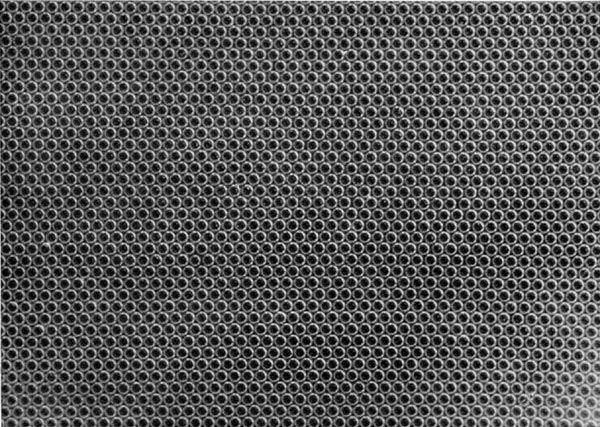
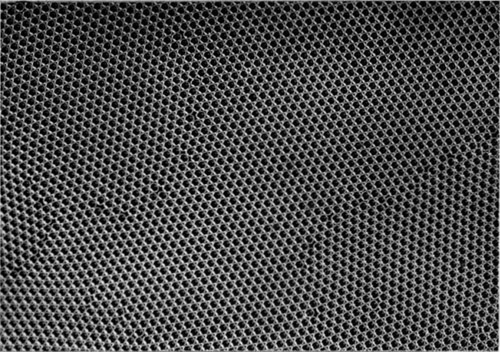
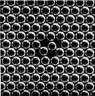
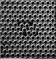
If the bubbles are allowed to accumulate in multiple layers on the
surface, they form a mass of three-dimensional ‘crystals’ with one of
the arrangements of closest packing. Figure 15, plate 18, shows an
oblique view of such a mass; its resemblance to a polished and etched
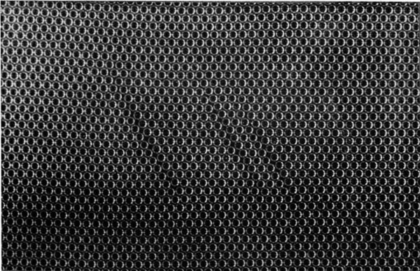
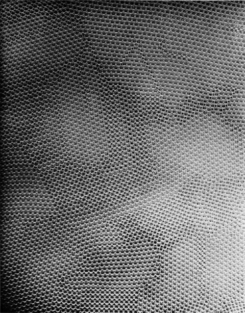
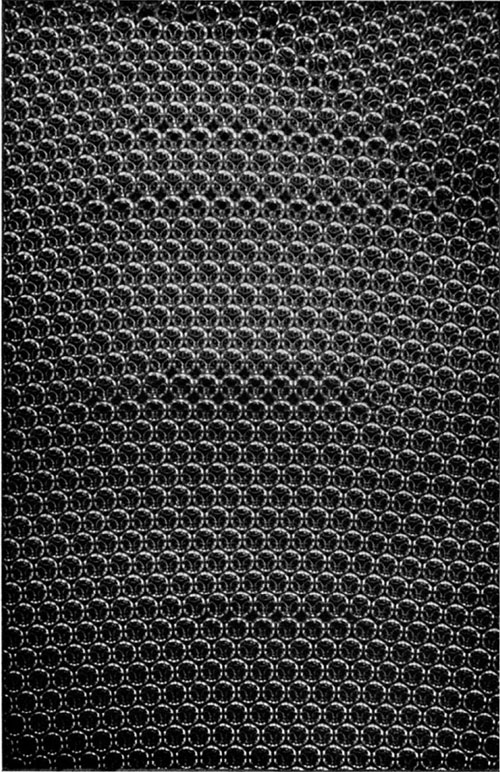
metal surface is noticeable. In figure 16, plate 20, a similar mass is
seen viewed normally. Parts of the structure are definitely in cubic
closest packing, the outer surface being the
Figure 18, plate 21, shows several dislocations in a three-dimensional structure subjected to a bending strain.
10. Demonstration of the model
With the co-operation of Messrs Kodak, a
In conclusion, we wish to express our thanks to Mr C. E. Harrold, of King’s College, Cambridge, who made for us some of the pipettes which were used to produce the bubbles.
| References |
| Bragg, W. L. 1942a Nature, 149, 511. |
| Bragg, W. L. 1942b J. Sci. Instrum., 19, 148. |
| Taylor, G. I. 1934 Proc. Roy. Soc. A, 145, 362. |
a.
b.
c.
d.
e.
f.
g.
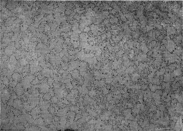
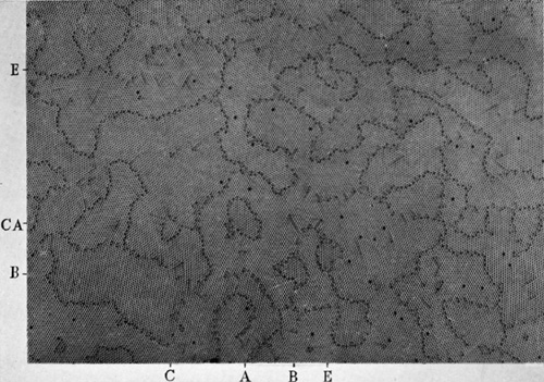
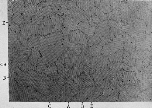
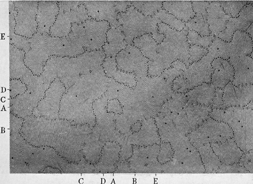
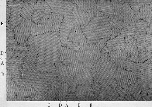
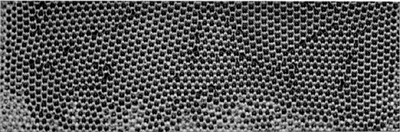
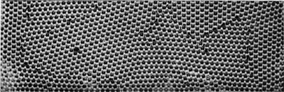
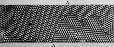
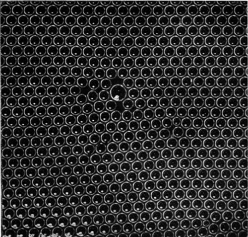
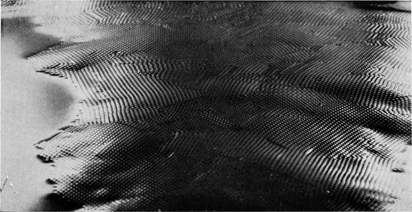
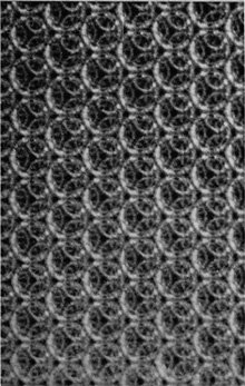
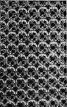
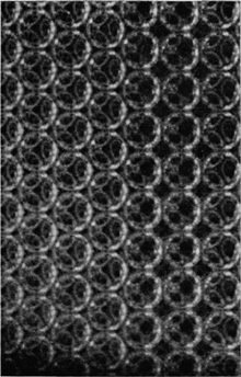
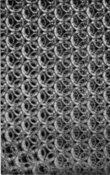
Figure 17
- At minute 48 in the recording of this lecture you can hear Feynman showing his students a film, which he narrates with a caveat, "I don't know everything that's in this movie. The movie comes without a soundtrack and I'm guessing what I'm looking at!" The film was Experiments with the Bubble Model of Metal Structure, 1952, by Sir Lawrence Bragg, W. M. Lomer, and J. F. Nye. The original 16 minute film had a soundtrack, but shorter silent versions were also produced. Two of the short versions and the original film, as well as others made about the Bragg-Nye Bubble Model of Metal Structure, are posted in a playlist on the YouTube channel of The Royal Institution of Great Britain. ↩